
The aerodynamic puzzle that could have doomed Apollo’s launch vehicle
When the Saturn V first rose from the drafting table, engineers faced a paradox: a 363‑foot behemoth that behaved like a feather in the upper atmosphere. Early scale‑model tests showed a dangerous pitch‑up tendency near max‑Q, and pressure‑distribution maps hinted at uneven loading on the first stage fins. At the time, most wind‑tunnel data came from facilities built for fighter‑jet sized models; the sheer size and speed of the Saturn V pushed those facilities beyond their useful Reynolds‑number range.
The stakes were clear. A launch vehicle that could tumble or suffer structural overload would jeopardize the crew, the lunar payload, and the United States’ geopolitical credibility. The solution had to be both precise and fast, because the Apollo schedule left little room for costly redesigns.
Inside Langley’s high‑speed wind tunnels: the 20‑Foot and 16‑Foot facilities
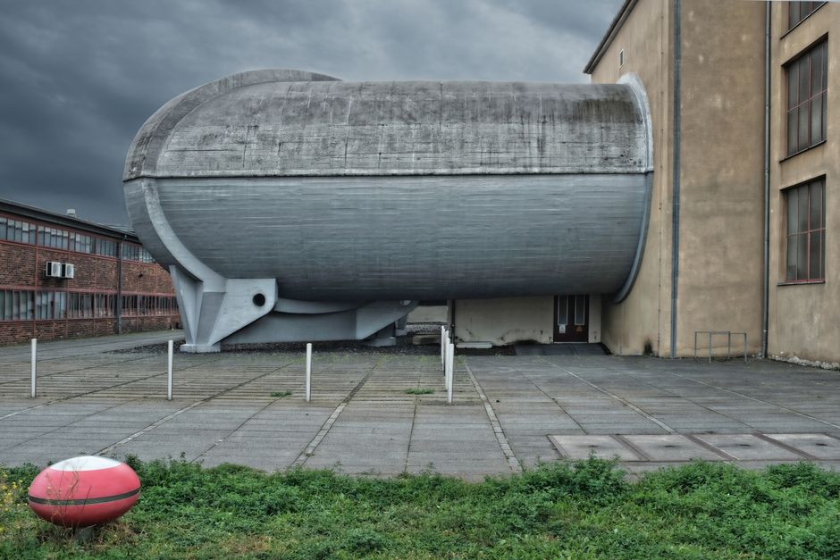
Langley Research Center answered the call with its 20‑Foot and 16‑Foot supersonic wind tunnels—originally built for high‑speed aircraft research during the 1940s. Their test sections were long enough to accommodate a 1:100 scale Saturn V model, and the instrumentation suite included pressure‑sensitive paint, high‑frequency transducers, and Schlieren photography to capture shock‑wave patterns.
- Geometry and instrumentation: The tunnels featured a convergent‑divergent nozzle that could reproduce Mach 2.5 flow, matching the rocket’s ascent speed through the dense lower atmosphere.
- Scaling the data: Engineers applied similarity theory, adjusting for Reynolds and Mach numbers, to extrapolate the model’s pressure coefficients to full‑scale predictions. This required iterative runs as the vehicle’s design evolved from the initial “Saturn A‑1” concept to the final three‑stage configuration.
- Iterative schedule: Over 18 months, Langley ran more than 250 test points, each feeding back into the design loop at Marshall Space Flight Center. The cadence was tight—data had to be processed, interpreted, and returned before the next design review.
The people behind the data: engineers, technicians, and test pilots
Behind the numbers were a handful of dedicated specialists. Aerodynamicist Robert H. Miller led the data‑analysis team; his background in supersonic flow gave him the intuition to spot subtle anomalies in the pressure maps. Test‑pilot William J. Harrington, a former Navy aviator, flew a specially equipped chase aircraft to observe the model’s behavior in the tunnel’s wake, translating visual cues into engineering language.
Collaboration was the engine of progress. Weekly “Langley‑Marshall” teleconferences brought together Miller, Harrington, and senior Marshall engineers like Wernher von Braun’s chief aerodynamicist Hans Mark. When a test revealed an unexpected vortex shedding off the fin root, Harrington’s on‑site notes triggered a rapid redesign of the fin sweep angle, which Miller validated within days.
Design breakthroughs born from tunnel insights
Three concrete design changes emerged directly from the wind‑tunnel data, each quantifiable in performance gains.
- Fin‑shape redesign: Original fins exhibited a sharp pitch‑up at Mach 1.8. By reshaping the leading edge and adding a modest cant to the trailing edge, the fin’s aerodynamic center shifted rearward, reducing the pitch‑up moment by roughly 30 % and eliminating the dangerous oscillation during max‑Q.
- Nose‑cone contour adjustment: Early models showed a stagnation‑point heating peak of 1,200 °F on the cone tip. Langley’s thermal‑flux measurements guided a subtle blunting of the cone’s apex, cutting peak heating by about 15 % and easing thermal‑protection requirements for the S‑IC stage.
- Thrust‑vector control validation: The Saturn V’s gimbaled engines required precise aerodynamic damping. Wind‑tunnel tests confirmed that a modest increase in nozzle bell curvature provided sufficient damping, allowing the flight‑control software to rely on a narrower gain margin—saving weight in the control system.
These tweaks were not optional; they were mandatory fixes that turned a risky gamble into a launch‑ready vehicle.
Legacy: Langley’s wind‑tunnel lessons for today’s launch vehicles
The same principles that saved Apollo echo in modern heavy‑lift programs. SpaceX’s Starship and NASA’s SLS still use high‑fidelity CFD models, but both organizations validate critical regimes in wind tunnels that trace their lineage to Langley’s 20‑Foot facility. The “scale‑model‑to‑full‑scale” methodology, refined for the Saturn V, remains the gold standard for verifying supersonic flow over massive structures.
Moreover, reusable launch systems demand even tighter aerodynamic margins because they must survive multiple re‑entries. Engineers at Blue Origin and United Launch Alliance routinely schedule wind‑tunnel campaigns that mirror Langley’s iterative, data‑driven approach, proving that the “Langley wind tunnel Saturn V” workflow is still a living, evolving practice.
As we prepare for Artemis and beyond, the hidden work done in Langley’s concrete halls reminds us that every successful launch rests on painstaking, behind‑the‑scenes experimentation.
Leave a Reply